3D Scanning File Output
There are many factors that go into determining the final quality and type of scan data output. That may explain the large variance in pricing that you will receive from different service bureaus. It all starts with the part that is being scanned. Surface reflection, color, surface finish, size, and type of geometry all affect the scanning results. Many times the part must be coated with a white powder before it can be scanned. The white powder helps the laser to bounce off of the part consistently. Shiny surfaces will deflect the beam and dark surfaces will absorb it. Most scanning systems can only capture "line of sight" geometry which means that deep cavities or hidden geometry can not be scanned.
The next factors in determining scan data caliber are the quality of the scanner calibration and the scanning parameters being used. If the scanner is not calibrated properly, the scan data will be inaccurate. Scanners collect thousands of measurement points of the geometry. There are many scanner settings that affect how many points will be collected and how accurate the points will be. Maximum scan angle, scan rates, scan density, exposure and amount of noise reduction all help to determine the quality of the scan and the amount of time it will take to scan your part.
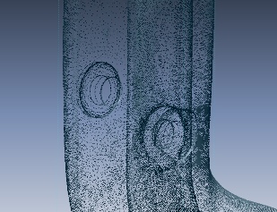
Point cloud data created from the 3D scanning process
After the part is scanned, the hard work begins. All of these points must be turned into a usable format. Regardless of what the final format will be, the first task that must be completed is to attach all of the points together with lines to create a mesh file. Again, there are many software parameters that will determine the quality and file size of the mesh data. Maximum edge length is one of the more important values. That will determine how close the points must be to one another before they are attached. If the value is too high, the mesh data will be choppy and inaccurate. If the value is too small, there will be many holes in the mesh data. Separate meshes from multiple scans must also be joined together. If the part or the scanner was moved between scans, this data must be accurately aligned before it is joined. This can be a time consuming process depending on the type of scanner and the software being used.
Raw Scan Data
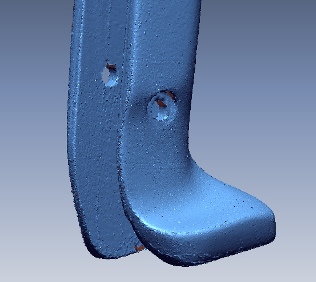
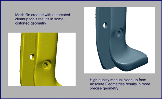
As you can see from this picture, raw scan data does not look very good. That is why software packages like Rapidform and Geomagic were created. These software tools help to clean up the mesh data. The skill and experience of the technician performing this work will determine the quality of the final output. There is some automation built into these software tools, but almost all mesh files must be fine tweaked to get a high quality output. There are smoothing tools that will make large surfaces look very good but will wash out fine features. Maintaining sharp corners on the mesh file is very difficult. Holes in the mesh must be filled in. Automated tools may or may not work for this. There is also the size of the file to be considered. Mesh files can be hundreds of megabytes in size. There are mesh decimation tools available to reduce the file size but if these are not used properly, the file may become choppy and inaccurate. Before selecting a service bureau, it may be a good idea to ask for a sample mesh file. Make sure the mesh file is from scan data and not from a re-engineered CAD file.
If your final requirement from the scanning process is an STL file, no further processing is required. If your requirements call for precise CAD data, it will be important to discuss exactly how the data will be used so that a decision can be made on how to proceed. Possible outputs are "dumb" IGES surface, "precise" IGES surface, STEP solid model, or Parametric solid model. The mesh data will be used as a guide to create the precise CAD file. See our File Output Selection Guide to help determine the type of file you will need.