Reverse Engineering of Injection Mold Tooling
Injection molding has been around since 1872, decades before CAD existed. There are many tools still in operation that have no CAD data. As those tools start to wear out and replacements are needed, many companies turn to 3D scanning for help in creating the CAD data.
Other reasons to use 3D scanning to digitally copy tooling include:
 Original production tooling was shipped from tooling source in Asia but the vendor would not supply the CAD data. The tool was damaged during production so a replacement cavity had to be manufactured.
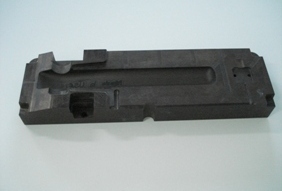
The customer sent the tooling to Absolute Geometries for 3D Scanning and Reverse Engineering.
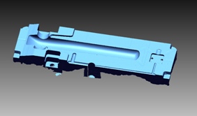 Absolute Geometries scanned the tooling with a Faro Laser Scanarm V3 producing a 3D mesh file with high accuracy and definition.
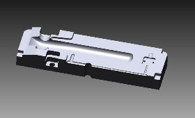 The new CAD file was created from the scan data. Absolute Geometries used Siemens NX to create the precise surfaces. The scan data was used as a guide when creating the surfaces.
Data from the NX file can be output in IGES, STP, or X_T formats. Absolute Geometries can also perform the modeling in SolidWorks or Pro Engineer and supply parametric solid models.